Acoustical Solutions’ move to a new location provided an opportunity to test our recommended room soundproofing products in a real-world environment.
Background
Acoustical Solutions, founded in 1989, has been a pioneer in offering a full array of acoustical products along with application advice to our customers since the beginning. Our commitment to educating our customers continues to this day.
During the COVID pandemic, many of our employees worked from home. However, in late 2022, as the pandemic waned, we decided to bring our entire team back together in the office. Unfortunately, the office was not large enough to handle the influx of our entire team as we had grown, so we began a search for a larger office space. In early 2023 we purchased a building built in the 1990s that had the office and manufacturing space that we required. However, it needed to be completely renovated. We hired an architect and a GC, and the renovation process took approximately 9 months. In the end, our entire team moved into the new space, and we were all together again.
The Test
Since we are an acoustical products company, we viewed this renovation as a chance to install and test the soundproofing capabilities of the products that we recommend to customers every day in a real-world office environment. To do that, we selected certain offices and conference rooms where maintaining confidentiality was important. We then soundproofed the walls and ceilings using various combinations of:
- Resilient Sound Isolation Clips (RSIC-1)
- AudioSeal® Mass Loaded Vinyl (MLV) Soundproofing Barrier
- PrivacyShield® ceiling tile barriers and light hood covers
- Green Glue Noiseproofing Compound
To get the most value out of this effort, we hired an acoustical engineer to test each treated wall structure so that we could have the data needed to educate our customers based on our own experience and test results. Here is a copy of the acoustical engineering report.
Two things make this project interesting from an acoustical products standpoint:
- The manufacturers of each of the products listed above have done their own tests to determine the soundproofing capabilities of their products in independent test labs that meet ASTM standards. We and they stand by those tests.
- However, we are not aware of anyone testing these products installed in combination in wall/ceiling structures to see how they performed in the “real world”. Based on our testing, we have come up with our “Good, Better, Best” recommendations for combining these products to achieve several desirable levels of soundproofing.
Acoustical Engineering Report Summary
Below is our office layout showing which walls were “soundproofed.” They include the President’s office, the HR Manager’s office, conference rooms, and one wall adjacent to the cafeteria. The “soundproof” walls are labeled A — Q:

Acoustical Solutions headquarters soundproof wall assembly locations
Below are images showing the actual wall construction done by our GC.

The rear and side walls of our Large Conference Room prior to acoustical product installation

Our installers trim the MLV to size before adding it to walls

A crew of three secures the very heavy roll of MLV to the studs

MLV is screwed onto the studs by our installer

Tape is applied to eliminate gaps between rolls of MLV

Green Glue is applied to the back of a second layer of drywall

The second layer of drywall with Green Glue on the back is placed directly over the first layer of drywall

The wall is now ready to be taped, spackled, and painted
Below are images showing the wall testing done by our acoustician.

A speaker is used to generate high-intensity broad-spectrum noise for testing in adjacent spaces.

A Decibel Meter and an Intensity Probe are used to measure sound leaking into the room

An Intensity Probe is used to determine sound leakage in a one square meter area of the wall
Based on the in-situ testing, the table below shows our “Good, Better, and Best” soundproof wall structure design recommendations along with the estimated NIC rating of each wall. Please note NIC rating is the “in the field” test result as opposed to an STC rating which is an “in the laboratory” test result. More details on the actual NIC test procedure used can be found in the test report.
| Rank | Wall | Construction | NIC | Summary |
| 9 | D | 2x Drywall — Green Glue — Studs — 1x Drywall | 48 | Useful — “GOOD” Performance |
| 8 | P | 2x Drywall — Green Glue — RSIC — Studs — MLV — 1x Drywall | 51 | Ignore — Construction Was Compromised |
| 7 | E | 1x Drywall — MLV — Studs — 2x Drywall — Green Glue | 55 | Useful — “Better” Performance MLV Adds 7 points (more than expected) |
| 6 | B,F,H,I M,N,O | 2x Drywall — Green Glue — MLV — Studs — 1x Drywall | 55 | Useful — “Better” Performance MLV Adds 7 points (more than expected) |
| 5 | A | 2x Drywall — RSIC Clips — Studs — 1x Drywall | 56 | Useful Alternative — “Better” Performance Alternative to Green Glue + MLV Combo |
| 4 | C | 2x Drywall — MLV — Studs — 1x Drywall | 56 | Ignore — Measurement Failures |
| 3 | G | 2x Drywall — Green Glue — MLV — Double Studs — 1x Drywall | 58 | Double Studs is points better than Single Studs |
| 2 | J | 2x Drywall — Green Glue — MLV — Studs — 2x Drywall — Green Glue | 61 | Useful — “Best” Performance — Add Green Glue Means Less Wall Thickness Extra layer of drywall + green glue is better than double studs |
| 1 | K | 1x Drywall — Masonry — 2x Drywall — Green Glue | 71 | Not Useful (masonry governs performance) |
Recommendations
Baseline
1 later of drywall with studs (typical wall construction)
This provides an STC between 30–40 (depending on your home’s construction).
Good
2 layers of drywall with Green Glue, studs, and 1 layer of drywall.
This provided an NIC 48 wall structure.

D Wall Assembly Diagram
We recommend this solution for the “noisy next-door neighbor problem” in a condo or apartment setting. This is the simplest retrofit install because no demo is required. This installation could be done as a DIY project. When complete, this approach will increase the NIC rating of the wall to 48. Hopefully, the noisy neighbor problem is taken care of.
Better
2 layers of drywall with Green Glue, studs, plus a layer of 1-lb./square foot MLV and 1 layer of drywall.
This provided an NIC 55 wall structure.

E Wall Assembly Diagram
2 layers of drywall, RSIC clips, studs, and 1 layer of drywall.
This provided an NIC 56 wall structure.

A Wall Assembly Diagram
Best
2 layers of drywall with Green Glue, studs, plus a layer of 1lb/square foot MLV and 2 layers of drywall with Green Glue.
This provided an NIC 61 wall structure.

J Wall Assembly Diagram
The “Best” construction is a few points better than using double studs (wall assembly “G” in the table above, which is the typical recommendation, especially for studios) and a single layer of drywall. Hence, the “Best” construction recommendation achieves more acoustic performance in a smaller wall thickness. Smaller wall thickness means more internal room square footage.
Achieving Optimal Results
Treating the walls is not enough! To achieve optimal room soundproofing results, all sound-flanking paths need to be considered. We learned during our renovation that building “soundproof” walls without treating all sound-flanking paths around doors, through open plenum ceilings, and around windows will not result in a “soundproof” room.
In our office renovation, the walls did not meet the ceiling decking and we had a drop tile ceiling design with typical cellulose-based ceiling tiles installed. To stop the sound from flanking over the walls and into the adjacent office, we installed our PrivacyShield® ceiling tile backers and light hood covers.
In all treated rooms, we also added Firestop Acoustical Putty Pads around receptacles (power outlets, light switches) to mitigate sound flanking through those small openings. Finally, in our Large Conference Room, we installed our PrivacyShield® Soundproofing Door Seal Kit (Complete Set) to mitigate sound flanking via the door.

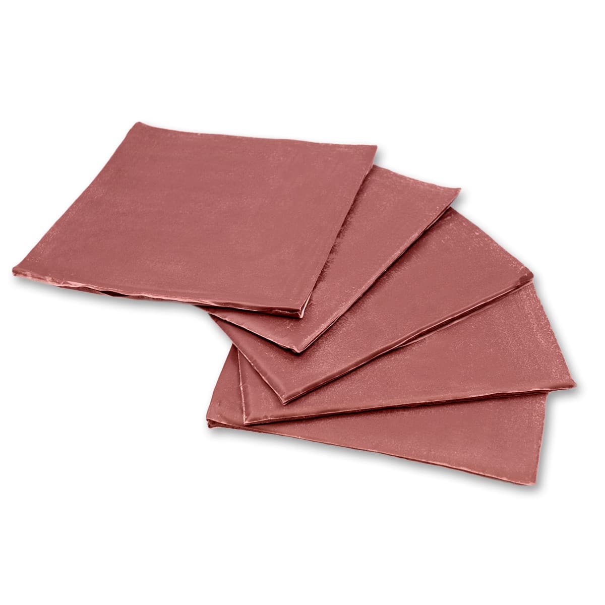
AudioSeal® Mass Loaded Vinyl Sound Barrier
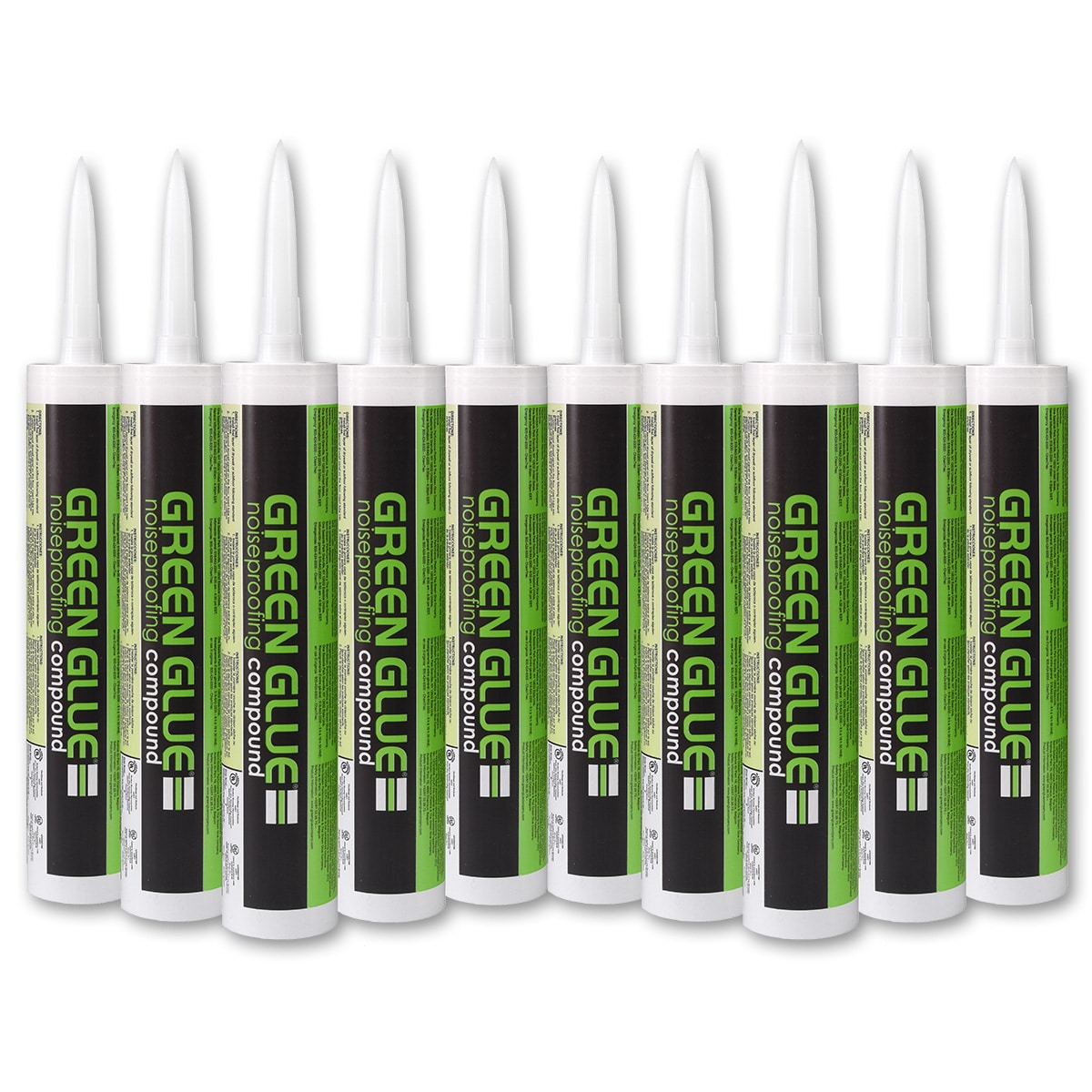
Green Glue Noiseproofing Compound – 28 oz. Tubes
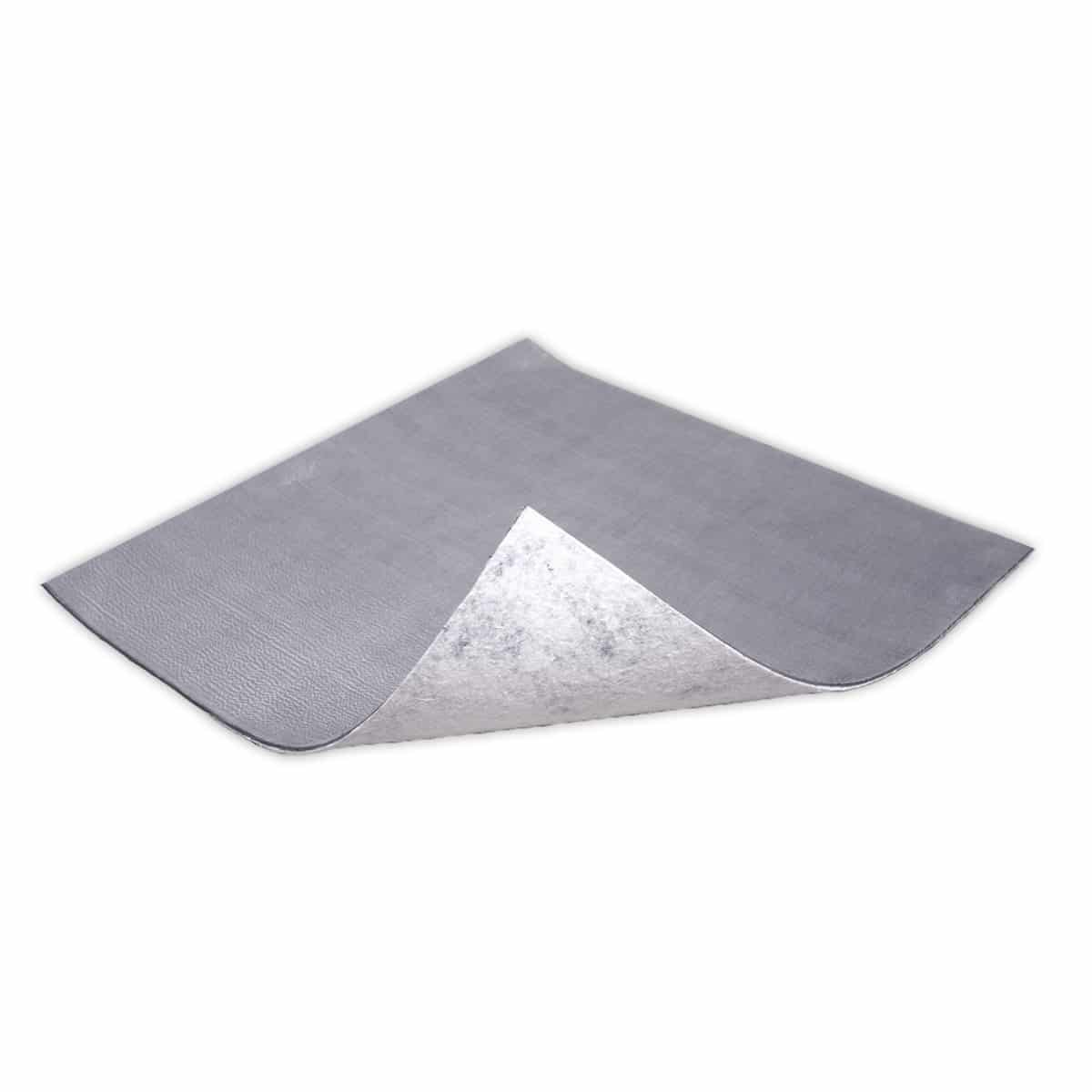
PrivacyShield® Ceiling Tile Barrier

PrivacyShield® Light Hood 2′ x 2′
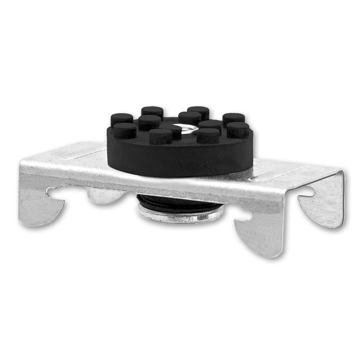
Resilient Sound Isolation Clip RSIC-1
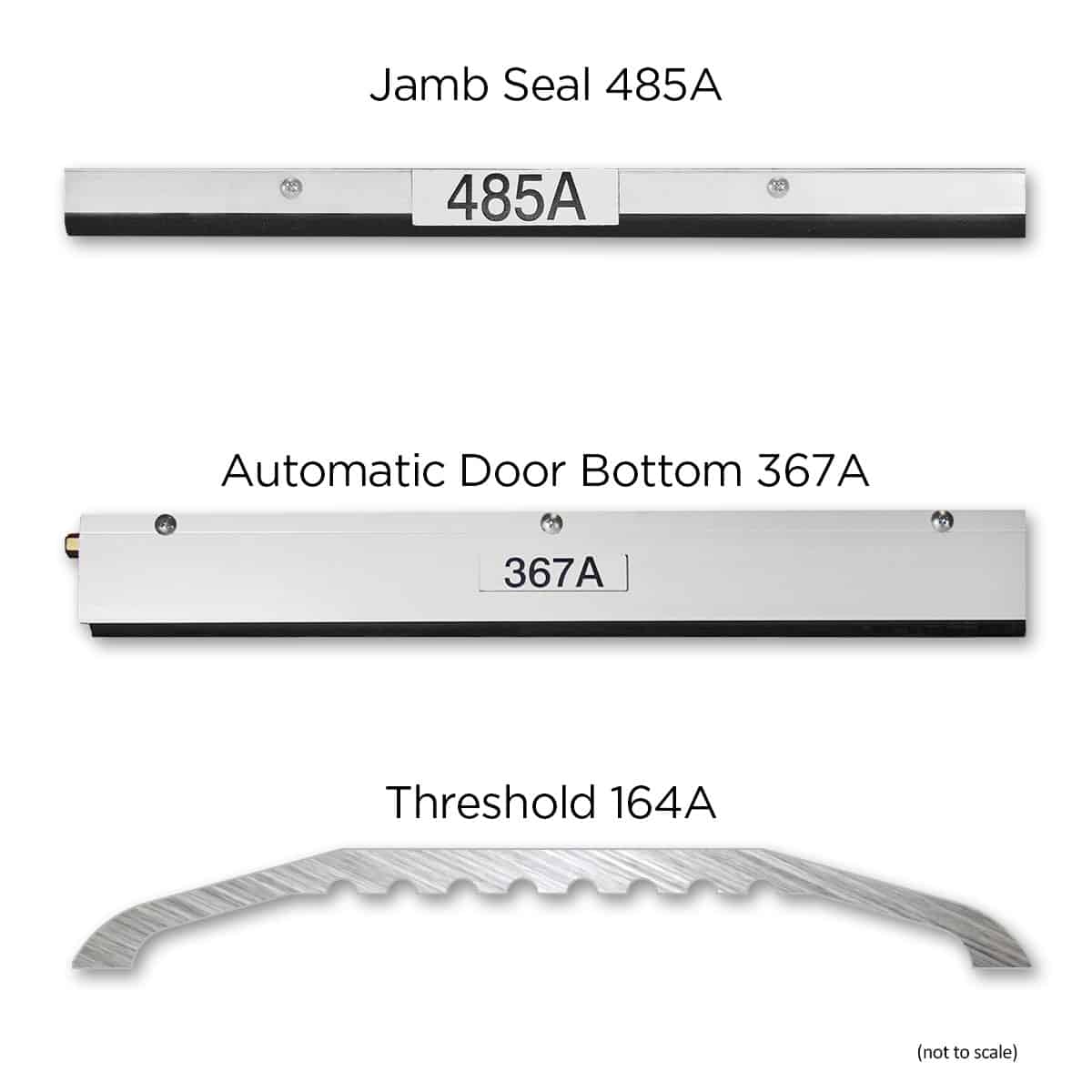
Acoustic Door Seal Kit (not to scale)
Firestop Acoustical Putty Pad (Single Gang)
Below are images showing prep work and installation of Ceiling Tile Barriers. Some extra work was needed before placing tiles around ductwork.

The size of the cut is traced onto the MLV side of the Ceiling Tile Barrier

Using a sharp knife, cut the shape out of the Ceiling Tile Barrier

A completed circle cutout in a Ceiling Tile Barrier

The Ceiling Tile Barrier is then cut in half and installed around ductwork, taping it down to eliminate air gaps

Both sides of the Ceiling Tile Barrier have been installed and taped down

An installer adds a sheet of Ceiling Tile Barrier directly over existing ceiling tiles, taping down as needed

Testing a Ceiling Tile Barrier for fit to see if any area needs to be taped down
Ceiling Treatment Test Measurements
As part of Acoustical Solutions’ dedication to being the leader in acoustic product knowledge, a series of tests were undertaken to measure the performance of the range of PrivacyShield® ceiling products. The intention was to gather knowledge of regularly recommended assemblies that were not covered by available literature from the individual material providers. These measurements conform to the ASTM E336 standard, and as such include measurement of flanking paths.
The rooms all had:
- Fully ducted ventilation systems
- Common plenum ceiling cavity
When treated, all had:
- Ceiling tile backers
- Lighting covered by ceiling tile backers
- Ventilation ducting lagged
- Ventilation aperture overlaid with ceiling tile backers
The table below shows the impact of adding this important layer of soundproofing to a soundproof room design.
| Location | NIC | Comments |
| Office 15 to Office 16 | ||
| No treatment | 33 | |
| Source Office Treated | 34 | Minor Improvement — Wall Becomes Dominant Flanking Path |
| Source & Receiver Offices Treated | 34 | No Improvement — Wall/Flanking Governs Performance |
| Large Conference Room to Office 24 | ||
| No Treatment | 30 | |
| Large Conference Room Treated | 39 | 9 Point Improvement — Ceiling is Main Flanking Path |
| Large Conference Room to Office 26 | ||
| No Treatment | 31 | |
| Large Conference Room Treated | 41 | 10 Point Improvement — Ceiling is Main Flanking Path |
Distilling the measurement results into several takeaways:
- Office 15 to Office 16 tests prove that walls must be treated in concert with the ceiling. There is no NIC improvement in the office space by only treating the ceiling.
- The conference room test shows a 10-point improvement to overall room performance when a high-performance wall is used along with treating the ceiling.
Final Touches
Below are images showing the final touches to our Large Conference Room.

Here you can see all three components of our Door Seal Kit (Complete Set)

The finished room has also been treated with our Acoustiwall Fabric Stretch System to reduce echo.

The finished room has also been treated with our Acoustiwall Fabric Stretch System on two walls to reduce echo.
Summary/Conclusions
I want to thank our product suppliers for providing us with the products that we used to do this “real world” in situ test. Two of the suppliers sent technical representatives to review the installation of their products to ensure they were installed correctly, met with our acoustical engineer to review his test procedure, and finally witnessed the testing to ensure the procedure was correctly followed. I appreciate their level of interest in ensuring our testing process had the technical rigor to provide valuable and repeatable results.
There are two key takeaways from our testing:
- The designer can combine readily available acoustical products to build “good”, “better”, and “best” soundproof wall structures in an open plenum drop tile ceiling office environment.
- Building soundproof walls without considering the other flanking paths in the room will result in suboptimal results for the overall room soundproofing performance.
If you would like to discuss our office renovation and the test results reviewed in this blog, please contact one of our sales team members at 1-800-782-5742.
To learn more about how Acoustical Solutions can solve your noise control problems, use our contact form, call one of our Acoustical Sales Consultants at (800) 782-5742, or visit us on the web at acousticalsolutions.com.